ROTARY UPS
|
A
flywheel driven rotary UPS is used for applications requiring
ride-through of short duration power system outages, voltage
dips, etc. The flywheel driven rotary UPS typically does not
include batteries, and support times are usually on the order of
a few seconds to a few minutes. The use of a generator driven
rotary UPS can provide extended power for an indefinite power
outage and also supply air-conditioning and lighting loads. Data
processing equipment rooms will typically overheat within a 15-
to 30-minute period if the ventilation system is not working,
making the generator set a near necessity for outages in excess
of this time. Analysis of battery cost will often justify a
generator set at lower cost than choosing a long battery support
time with an accompanying restriction of eventually implementing
an orderly critical load shutdown. A battery support time of as
little as a few minutes may be specified with generator set
backup; however, longer support times in the range of 15 minutes
are more typical.
|
|
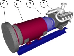
Basic Principle Diagram
|
|
1)
Diesel engine
|
3)
Electromagnetic clutch
|
6)
Synchronous motor /alternator
|
| 4)
Flywheel |
|
|
Some of rotary UPS
systems consists of an AC Motor Generator (M-G) set with a
flywheel, as well as a rectifier, storage batteries, inverter,
static switch and solid state circuitry. Both the motor
generator set and the rectifier/battery/inverter combination are
supplied by the incoming utility service. They represent
parallel supply paths and either path is capable of supplying
the load. A static switch selects the path to be utilized to
supply the load. During normal operation, the M-G set powers the
computer loads, while the off-line static section is on
"stand-by" and charges the system batteries. Upon loss
of the utility feed, the control circuitry will disconnect the
M-G set from the utility by opening the static switch and
closing the inverter-output circuit breakers, allowing the
system batteries to power the M-G set through the inverter.
Mechanical energy "stored" in the flywheel allows the
M-G set to continue to deliver its full-rated output for
(generally) a minimum of 200 milliseconds. This provides
sufficient time for the control system to sense a loss of
utility supply and to transfer to the battery/inverter
combination for supply of loads.
|
|
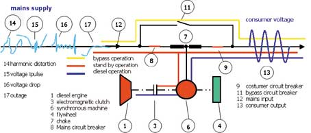
Basic schematic diagram
|
|
Sources:
- US
Army Corp of Engineers
- AKF Engineers
- The figures are from
Hitzinger GmbH
|
|